
Richard D Peters
formerly of Brunel University & Arup, currently Peters Research Ltd
This paper was presented at ELEVCON HONG KONG 1995, The International Congress on Vertical Transportation Technologies and first published in the IAEE book “Elevator Technology 6”, edited by G.C. Barney. It is reproduced with permission from The International Assocication of Elevator Engineers. The paper was republished by Elevator World (December 1996), and by Elevatori (May/June 1997). This web version © Peters Research Ltd 2009.
Abstract
The formulae presented in this paper allow analysis of any peak passenger traffic flow for any practical configuration of double decker lifts. A Poisson approximation of passenger arrivals at lift landing stations is assumed, enabling the derivation of formulae for probable number of stops and average reversal floors during a lift round trip. Double decker round trip time calculations yield analysis results in terms of coincident stops, waiting interval, handling capacity and capacity factor. Derivation and implementation of the General Analysis formulae are discussed. Examples are analysed using the Oasys LIFT program which utilises the formulae.
1 Introduction
Double decker lifts have two separate cabs built into a single unit so that the upper and lower cabs serve adjacent floors simultaneously. During peak periods maximum operating efficiency is achieved by restricting the lower cabs to serving odd numbered floors, and the upper cabs to serving even numbered floors.
Double decker lifts provide greater handling capacity per shaft than conventional lifts. This is particularly attractive for high rise buildings.
The sacrifice is that double decker lifts are less convenient for passengers. Occupants of even numbered floors are required to use escalators to reach the upper lift cab on their way into the building. And again to reach the exit on their way out. Passengers have to walk one storey when an inter-floor trip from an odd to an even numbered floor, or vice-versa, is made. To alleviate this problem, double decker lift control systems can provide an odd-even floor service by operating in alternative modes out of peak times.
2 Double decker travel calculations
2.1 Previous Work
G R Strakosch provides an example double decker lift calculation in his book Vertical Transportation, Elevators and Escalators(1). An office block up peak with an element of down-peak traffic is analysed. Strakosch assumes that the lift will stop at every possible stop on its journey up the building, and once on its way down. Round trip time calculations follow the procedure defined for single deck lifts, with minor adjustments to take into account the fact that two cabs are loading simultaneously.
G T Kavounas presents new formulae for up peak double decker analysis in Elevator World(2). Kavounas modifies the equations given by G C Barney and S M dos Santos in Elevator Traffic Analysis(3) for single deck up peak traffic analysis. Double decker lift equations for probable number of stops and highest reversal floor are derived. A new variable, Figure of Merit is introduced. This is defined as the percentage of stops that are coincident to both lift cabs (if the lift stops and passengers enter and/or exit from both cabs, then the stop is coincident). A high proportion of coincident stops is preferred as non-coincident stops are frustrating for passengers left waiting when no-one is entering or leaving their lift cab. Kavounas demonstrates good consistency with Strakosch’s work.
2.2 General Analysis
The General Analysis double decker lift calculations presented in this paper allow any peak passenger traffic flow to be considered for any practical configuration of double decker lifts. This allows us to consider up peak, down peak, two-way, and interfloor traffic as well as any special cases. The analysis is an extension of the General Analysis lift calculations for conventional, single deck lifts previously presented by the author(4)(5).
3 Defining lift traffic
Before carrying out any analysis, we need to be able to define the peak passenger traffic flow using the system. To define passenger flow completely we need two terms, arrival rate and destination probabilities. A passenger arrival rate is required for each floor at which passengers arrive over the peak period. Each arrival rate has a corresponding set of destination probabilities defining the likely destinations of passengers joining the lift at that floor.
A morning up peak for a 22 storey office building with double decker lifts could be represented diagrammatically as shown in Figure 1. This example assumes an evenly distributed population of 2666 people over levels 3 to 22 and five minute handling capacity of 16% (16% of 2666 = 427 people per 5 minutes).
A more complex traffic flow is described in Figure 2. Here we consider a lunchtime peak in an office building where there are double storey conference and restaurant facilities on the top two floors. Consider the scenario when a morning conference ends during the lunch time peak. Conference delegates are visitors to the building. The peak traffic is a combination of:
i. resident passengers travelling from their offices to the restaurant for lunch
ii. resident passengers travelling back to their offices after lunch
iii. resident passengers travelling to the ground floor to leave the building to buy sandwiches or eat out
iv. resident passengers returning from buying/eating lunch out
v. visitors leaving the conference facility
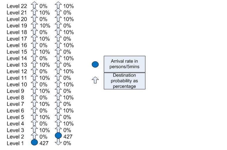
Figure 1 Morning incoming up peak for 22 storey office block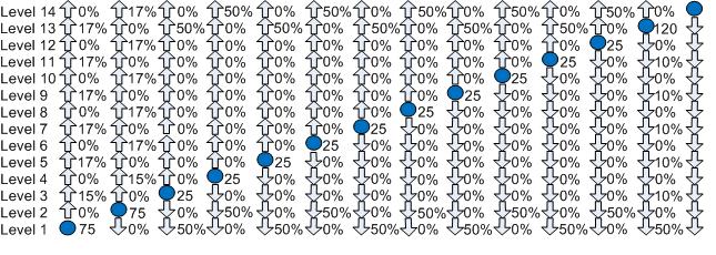
Figure 2 Office block lunchtime peak with restaurant and conference facility on top two floors
4 Derivation of double decker general analysis formulae
Consider the term, p(n)i,j which is the probability of n passengers wanting to travel from the ith to the jth floor in the time interval T. It is generally accepted that the arrival of passengers at a lift landing station is reasonably approximated by a Poisson process(3). This gives us the result:
where i is the passenger arrival rate in persons s-1 and di,j is the destination probability from the ith to the jth floor.
When dealing with probabilities it is generally easier to calculate the probability of an event not happening, and then subtract this from 1 to arrive at the probability of the event happening. So, if we let

we get

The same result was derived for the single decker lift General Analysis(4)(5). But note that for the double decker analysis, destination probabilities from odd to even floors and vice-versa will always be zero (see Figures 1 and 2).
The probability of the lift stopping on the jth/j+1th floor on its way up is:
1 – (probability of no calls from lower floors to j or j+1)*(probability of no calls from floors j or j+1 to upper floors)
Mathematically we can express this:
Applying this and similar principles we can derive a set of formulae for probable number of stops, highest and lowest reversal floors. To determine capacity factor, the average number of people entering and exiting upper/lower lift cabs is calculated at each floor of the round trip. Formulae are given in the appendix to this paper. As demonstrated by Kavounas, conventional round trip time formulae can be applied, with minor modifications to suit double decker operation.
5. Computer implementation
General Analysis calculations are iterative as equations for probable number of stops and reversal floors are dependant on the waiting interval and vice-versa. The flow chart in Figure 3 demonstrates this iteration and suggests a possible computer program structure.
Figure 3 Program Flow Chart
Single deck General Analysis traffic calculations have been implemented and extensively applied using the Oasys (Ove Arup Computer Systems) LIFT program since 1989. The General Analysis double decker lift calculations have been implemented in the latest version of Oasys LIFT.
5 Examples
5.1 Up Peak Example
Consider a 22 storey office building with 2000 m2 net usable area per floor where the 5 minute handling capacity required is 16%. Analyse the performance of 8 No 2.5 m/s, 1800 kg/1800 kg lifts. Assume the following additional parameters:
Population density 1 person per 15 m2 Door operating times 1.8 s open, 2.9 s close
Storey height 3.6 m Acceleration 0.8 m/s2
Passenger weight 75 kg Jerk 2 m/s3
Passenger transfer 1.2 s in, 1.2 s out Motor start up delay 0.5 s
Round Trip Time 5 % inefficiency
An analysis based on the Oasys LIFT 6.0 implementation of the General Analysis and Kavounas’ formulae has been carried out be the author. The results are summarised as follows:
The results show a high degree of consistency for the up peak analysis.
5.2 Complex Example
For more complex example consider the second peak traffic scenario described in section 3 and in Figure 2. Assuming 8 No 2.5 m/s 1250 kg/1250 kg lifts and the following additional input parameters:
Storey height 3.6 m Door operating times 1.8 s open, 2.9 s close
Acceleration 0.8 m/s2 Passenger weight 75 kg
Jerk 2 m/s3 Passenger transfer 1.2 s in, 1.2 s out
Motor start up delay 0.5 s Round Trip Time 5 % inefficiency
Oasys LIFT 6.0 gives the following results:
Capacity Factor 68 % Probable Number of Stops 11.9
Waiting Interval 26.7 s Lowest Reversal Floor 1
Figure of Merit 83% Highest Reversal Floor 13
6 Conclusions
The General Analysis provides us with a tool to analyse any peak traffic for any practical configuration of double decker lifts. Consistency has been demonstrated with other conventional analysis techniques for a simple up peak analysis.
ACKNOWLEDGEMENTS
The author would like to thank his supervisors, lecturers and colleagues at Brunel University, Ove Arup & Partners and the CIBSE Lift Group for sharing their knowledge and experience which are providing an excellent basis for his research. The author acknowledges, with gratitude, financial support from the Engineering and Physical Sciences Research Council, The Ove Arup Partnership, and the Chartered Institution of Building Services Engineers.
REFERENCES
- Strakosch G R Vertical Transportation: Elevators and Escalators 2nd edn (New York: J Wiley & Sons Inc.)(1983)
- Kavounas G T Elevatoring Analysis with Double Deck Elevators Elevator World 11/89 pp65-72 (November 1989)
- Barney G C and dos Santos S M Elevator Traffic Analysis Design and Control 2nd edn (London: Peter Peregrinus)(1985)
- Peters RD Lift traffic analysis: Formulae for the general case CIBSE Building Service Engineering Research and Technology Volume 11 Number 2 (1990)
- Peters RD The Theory and Practice of General Analysis Lift Calculations Elevator Technology 4, Proceedings of ELEVCON ’92 (The International Association of Elevator Engineers)(1992)